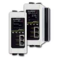
G478 Isolator

Frequency Input, Field Configurable Isolator – G478

Categories: ,

Product Description

G478 Isolator

G478 Isolator

The G478 is a DIN rail mount, frequency input signal conditioner with 1800VDC isolation between input, output and power. The field configurable input and output offer flexible, wide ranging capability for variable frequency drives, magnetic pick-ups, turbine flow meters, and other pulse or frequency output transducers.

The input of the G478 can be configured for any frequency span from 2Hz to 10,000Hz. The input amplitude threshold sensitivity can be adjusted from 150mVp to 10Vp to ensure accurate frequency measurement and minimize transient noise related errors. The maximum input amplitude is 150 Vrms. The output can be set for 0-5V, 0-10V, 0-1mA, 0-20mA or 4-20mA.

The G478 to be field configured for virtually any frequency input to DC signal output within the ranges specified. Calibration utilizes ‘Touch-Cal’ technology in which the user simply applies the minimum and maximum input frequencies, and touches a recessed button to configure the corresponding minimum and maximum output range.

The Ultra SlimPak housing allows installation of up to 24 units per linear foot. The wide ranging power supply is inverter isolated and accepts any voltage between 9 and 30VDC.

Application

The G478 is useful in eliminating ground loops and interfacing pulse output transducers, such as turbine flow meters and magnetic pick-ups, to data acquisition and control systems.

Advanced digital technology, combined with Action’s ASIC technology, provide a stable output at low frequencies for higher accuracy.

Touch-CAL Technology

To precisely adjust the output, the user adjusts the input frequency while the OUTPUT LED is lit until the desired output level is achieved. The output levels are locked-in by pushing the CAL button. Status LEDs show the operation mode of the device.


Status LEDs

The G478 utilizes three status LEDs.

The green LED varies intensity as the frequency changes from 0 to 100% of full scale range (e.g., for a configuration of 0-1000Hz, the LED will be off with an input of 0Hz and fully illuminated at 1000Hz. With an input of 500Hz, the LED will be dim). If the input signal is 10% more than full scale range (overranged), the LED will flash at 8Hz.


The yellow INPUT LED denotes input programming modes.


The red OUTPUT LED denotes output programming modes (see Configuration, Calibration and Figure 2 for details).

Configuration

Any 2Hz range from 0 to 10,000Hz can be converted to a full scale output signal (e.g. 0- 2Hz/4-20mA or 9998-10,000Hz/4-20mA).


Unless otherwise specified, the factory presets the Model G478 as follows:


Input Range: 0 to 1000Hz
Sensitivity: 1V RMS
Output Range: 4 to 20mA


Note: “Sensitivity” refers to the noise rejection level ( the trigger threshold) of the input.


For other I/O ranges, refer to Table 1 and 2. For calibration mode reference, see the stepby- step flow chart in Figure 4.


  1. With DC power off, choose the desired output voltage/current range from Table 1 and set position 1 through 8 of SW1.
  2. Set the Input sensitivity switch (SW1, 9 & 10) to LO for input amplitudes between 150mVp and 50Vrms, with noise rejection to 1Vp. Set the switch to HI for input amplitudes between 500mVp and 150Vrms, with noise rejection up to 10Vp (see Table 2).
Calibration
  1. Connect the input to a calibrated frequency source and apply power. Wait 1 hour for thermal stability before monitoring the voltage or current output.
  2. Adjust the input frequency to the desired maximum and observe that the ouput has increased and is sensing the input. If the output does not increase, turn the sensitivity potentiometer in a counter-clockwise direction until the output begins to change proportionally to the input, plus another full turn.
  3. Press the CAL button once to enter the calibration mode. The yellow and green LEDs will be on.
  4. Input the maximum desired frequency and press the CAL button to store. The yellow LED will now be the only LED on.
  5. Input the minimum desired frequency and press the CAL button to store. The green and red LEDs will now be on.
  6. To precisely adjust the maximum output, adjust the input frequency until the output reads within +0.1% of the maximum selected output range. This typically occurs near 90% of the HI input frequency. Press the CAL button to store the value. The red LED will now be on.
  7. To precisely adjust the minimum output, lower the input frequency until the output reads within +0.1% of the minimum selected ouput. This typically occurs near 10% of the HI input frequency. Press the CAL button to store the value. All three LEDs will be on.
  8. Press the CAL button one final time to exit the calibration mode. The green LED will now be on.
  9. Check the minimum and maximum input-tooutput calibration. Repeat steps 1 through 8 if calibration is not within desired specifications.

Optimal Sensitivity

If the amplitude of the input frequency is within the sensitivity parameters (i.e. 150mVp – 1Vp for LO and 0.5Vp – 10Vp for HI), then the sensitivity parameters can be set for optimum noise rejection:


  1. Set the input near midrange (50% input) or to a frequency that exhibits the minimum pulse amplitude.
  2. Turn the sensitivity pot (SENS) clockwise (CW) until the output drops to minimum.
  3. Turn the sensitivity pot counterclockwise( CCW) a turn or two until the output returns to the previous level.
  4. Run the input through the full frequency range to make sure that the pulses are sensed at both the low and high input frequencies. If the output drops out during this test (and the input freq. >0%) then turn the sensitivity pot counter-clockwise another turn or two until the output picks up. Repeat to validate sensitivity settings.
TECHNICAL SPECIFICATION (G478)

Frequency Input

  • Full Scale Range: 2 Hz minimum from 2Hz to 10,000Hz.
  • Amplitude Range: Range: 150mVp to 150Vrms
  • Impedance: >10K Ohms
  • Over-voltage: 180Vrms, max.
  • Over-range: 20KHz, max.


  • Common Mode (Input to Ground):   1800VDC, max.


  • Zero Turn-Up: 99% of full scale range (9998Hz)
  • Span Turn-Down: 99% of full scale range (2Hz)


Output

  • Voltage Output: 0-5V, 0-10V
  • Source Impedance: <100 Ohms
  • Drive: 10mA, max. (1K Ohms, min. @ 10V)
  • Current Output: 0-1mA, 0-20mA, 4-20mA
  • Source Impedance: >100K Ohms
  • Compliance: 0-1mA; 7.5V, max. (7.5K Ohms, max.)
    • 0-20mA; 12V, max. (600 Ohms, max.)
    • 4-20mA; 12V, max. (600 Ohms, max.)


Accuracy Including Linearity, Hysteresis +0.1% of selected range at 25°C.


Stability

+0.025%/°C maximum of selected range.


Response Time (10 to 90%)

3 input cycles + 250ms


Common Mode Rejection

  • DC: 100dB
  • >60Hz: 80dB

Isolation

1800VDC between input, output and power.


EMC Compliance (CE Mark)

  • Emissions: EN50081-1
  • Immunity: EN50082-2
  • Safety: EN50178


LED Indication

  • LEVEL (green): lit when power is on
    • Input > 110% then 8Hz. flash
    • Input < -10% then 4Hz flash
  • INPUT (yellow):input range programming status
  • OUTPUT (red): output range programming status


Humidity (Non-Condensing)

  • Operating: 15 to 95% @ 45°C
  • Soak: 90% for 24 hours @ 65°C


Temperature Range

  • Operating: 0 to 55°C (5 to 131°F)
  • Storage: -25 to 70°C (-13 to 158°F)


Power

  • Consumption: 1.5W typical, 2.5W max.
  • Range: 9 to 30VDC


Weight

0.50 lbs


Wire Terminations

Screw terminals for 12-22 AWG


Agency Approvals

  • CSA certified per standard C22.2, No. 0-M91 and 142-M1987 (File No. LR42272).
  • UL recognized per standard UL508 (File No.E99775).
  • CE Conformance per EMC directive 89/336/EEC and Low Voltage 73/23/EEC (Input < 75Vp or < 50Vrms, only).
Ordering Information
1. Specify: Model: G478-0001
2. Accessories: (see accessories)
3. Optional Custom Factory Calibration: specify C620 with desired input and output range
Accessories
All SlimPak “G” Series modules will mount on standard TS32 (model MD02) or TS35 (model MD03) DIN Rail. In addition, the following accessories are available:
HS01 Heat Sink
MD03 TS35 x 7.5 DIN rail
WV905 24VDC Power Supply (0.5 Amp)
H910 24VDC Power Supply (1 Amp)
H915 24VDC Power Supply (2.3 Amp)
MB03 End Bracket for MD03
C664 I/O Descriptive Tags