Product Description
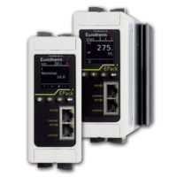
G448 Signal Conditioner
G448 Signal Conditioner
The G448 is a DIN rail mount, bridge or strain gauge input signal conditioner with 1800VDC isolation between input, output and power. The field configurable input and output offer flexible, wide ranging capability for bridge or strain gauge input applications from 0.5mV/V to over 50mV/V.
Wide ranging, precision zero and span pots allow 50% adjustablity of offset and gain within each of the 11 switch selectable input ranges. The output can be set for either 0-5V, 0-10V, 0-1mA, 0- 20mA or 4-20mA.
Application
Three way isolation in the G448 completely eliminates ground loops from any source. Isolation protects expensive SCADA systems from ground faults and provides filtering for noise reduction which can be a significant problem with small, millivolt, bridge signals. Wide ranging flexibility allows the user to easily zero out dead-loads in weighing systems or configure bipolar input ranges for expansion-compression or vacuum-pressure bridge applications.
Diagnostic LED
The G448 is equipped with a dual function LED signal monitor. The green, front mounted LED indicates both DC power and input signal status. Active DC power is indicated by an illuminated LED. If the input signal is more than 110% of the full scale range, the LED will flash at 8Hz. Below -10%, the flash rate is 4Hz.
Configuration
The G448 has 11 input range switch settings. Trim potentiometers allow 50% input zero and span adjustablity within each of the 11 full-scale, input ranges.
For example, the 200mV switch setting in Table 1 configures the input for a 0 to 200mV range. Since the span can be contracted by 50%, this enables an input span as narrow as 100mV of the range, or 50%. This span can be positioned anywhere within the 0-200mV range with a zero off-set as large as 50% of the full scale range (e.g. 100 to 200mV input).
Unless otherwise specified, the factory presets the Model G448 as follows:
| Input Setting: | 0 to 50mV |
| Input Range: | 0 to 30mV (3mV/V) |
| Excitation: | 10V |
| Operation: | Direct |
| Output: | 4 to 20mA |
The DC power input accepts any DC source between 18 and 30V, typically a 24VDC source is used (see Accessories).
For other I/O ranges refer to Tables 1 through 4 and reconfigure switches SW1 and SW2 for the desired input range, function, excitation and output range.
Calibration
- After configuring the DIP switches, connect the input to a calibrated millivolt source. Connect the output to the device (or a load equivalent to the device) and apply power. (see Wiring Diagram, Figure 2 or 3).
- Set the calibrator to the desired minimum and adjust the zero potentiometer for the desired minimum output.
- Set the calibrator to the desired maximum and adjust the span potentiometer for the desired maximum output.
- Repeat steps 2 and 3, if necessary for best accuracy.
TECHNICAL SPECIFICATION (G448)
Input Voltage
- Full Scale Range: 10mV to ±200mV
- Impedance: >1M Ohms
- Overvoltage: intermittent 400V, max.; continuous 264V, max.
Common Mode (Input to Ground) 1800VDC, max.
- Zero Turn-Up: 50% of full scale range
- Span Turn-Down: 50% of full scale range
- Operation: direct or reverse acting
Output Voltage
- Output: 0-5V, 0-10V
- Impedance: <10 Ohms
- Drive: 10mA, max. (1K Ohms, min. @ 10V)
- Current Output: 0-1mA, 0-20mA, 4-20mA
- Impedance: >100K Ohms
- Compliance: 0-1mA; 7.5V, max.(7.5K Ohms, max.)
- 0-20mA; 12V, max. (600 Ohms, max.)
- 4-20mA; 12V, max. (600 Ohms, max.)
Bridge Excitation
1 to 10VDC, 120mA max.
Accuracy Including Linearity, Hysteresis ±0.1% typical, ±0.2% maximum of selected input range at 25°C.
Stability
±0.025%/°C typical, 0.05%/°C maximum, of selected full scale input range.
Output Noise (maximum)
0.1% of span, rms, or 10mV whichever is greater.
Response Time (10 to 90%)
<200mSec., typical.
CMRR
DC to 60Hz: >120dB, >100dB for 0 -1mA range
Isolation
1800VDC between input, output and power.
EMC Compliance (CE Mark)
- Emissions:EN50081-1
- Immunity:EN50082-2
- Safety: EN50178
LED Indication (green)
Input Range (approx.)
- >110% input: 8Hz flash
- <0% input: 4Hz flash
Humidity (Non-Condensing)
- Operating: 15 to 95% @ 45°C
- Soak: 90% for 24 hours @ 65°C
Temperature Range
- Operating: 0 to 55°C (32 to 131°F)
- Storage: -25 to 70°C (-13 to 158°F)
Power
- Consumption:
- 2.5W typical (one 350 Ohm bridge),
- 4W max. (four 350 Ohm bridges).
- Range: 18 to 30VDC
Weight
0.54 lbs.
Wire Terminations
Screw terminals for 12-22 AWG
Agency Approvals
- CSA certified per standard C22.2, No. 0-M91 and 142-M1987 (File No. LR42272).
- UL recognized per standard UL508 (File No.E99775).
- CE Conformance per EMC directive 89/336/EEC and low voltage 73/23/EEC.