Product Description
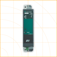
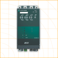
G428 ultra slimpak
G428 ultra slimpak
The G428 is a DIN rail mount, thermocouple input signal conditioner with 1800VDC isolation between input, output and power. The field configurable input and output offer flexible, wide ranging capability for J, K, T, R, S, E and B type thermocouples.
The input of the G428 can be configured for over 60 different thermocouple temperature ranges (see Table 6). The output is linear to temperature and can be set for either 0-5V, 0-10V, 0-1mA, 0- 20mA or 4-20mA.
For an RTD and thermocouple input temperature transmitter with improved accuracy and stability, see Action I/Q model Q488. PC or DIP switch programmable.
Wide ranging, precision zero and span pots allow 50% adjustablity of offset and span turn-down within each of the ranges. For example, the 0-1000°C range could be offset and turned down to provide a 4- 20mA signal representing 500-1000°C. Similarly, adjustment can be referenced to the output range. The example from above could be used to provide a 12-20mA signal from a 750 to 1000°C temperature input.
Application
The G428 field configurable thermocouple input isolator is useful in eliminating ground loops and interfacing thermocouple sensors to data acquisition and control systems.
Three way isolation completely eliminates ground loops from any source. Isolation protects expensive SCADA systems from ground faults and allows the noise reduction benefits of grounded thermocouples to be realized.
The G428 employs the latest in advanced analog signal processing technology. In addition to its multiple microprocessors, a special ASIC* chip is used for high accuracy and reliability. The G428 is also equipped with cold junction compensation (CJC) circuitry to provide ice-point reference. Upscale or downscale thermocouple burnout detection is switch selectable.
High density DIN rail mounting offers an extremely compact solution to save valuable panel space.
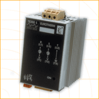
Diagnostic LED
The G428 is equipped with front panel LEDs for INPUT (green), TROUBLE (yellow) and CAL OK (yellow). At start-up, both the INPUT and the CAL OK LEDs flash alternately for 10 seconds while start-up takes place.
Input LED
This green LED is lit continuously when the input is within the specified range. In the full temperature range setting, for the over range condition the LED flashes at 8Hz, whereas for the under range condition it flashes at 4Hz. In a sub-range temperature setting, for the over range condition the LED flashes at 1Hz, whereas for the under range condition it flashes at 0.5Hz.
Cal ok LED
This yellow LED is continuously on when the device is calibrated.
Trouble LED
This yellow LED is off during the normal operation of the device. Consult factory if this LED is on, indicating a microprocessor malfunction.
Configuration
A major advantage of the G428 is its wide ranging capabilities and ease of configuration. The G428 offers 50% input zero and span adjustablity within each of the full-scale input ranges.
Unless otherwise specified, the factory presets the Model G428 as follows:
| Input: | J-type |
| Range: | 0 to 500°C |
| Output: | 4 to 20mA |
| Burn Out: | Upscale |
The DC power input accepts any DC source between 9 and 30V; typically a 12V or 24VDC source is used (see Accessories).
For other I/O ranges refer to Tables 1 through 6 and reconfigure switches SW1 and SW2 for the desired input type range and output.
- Choose the desired temperature range from table 6, then use table 1 and 2 to configure the switches, as described in the following steps, for thermocouple type and range.
- With DC power off, position input switches 1 and 2 on “SW2” for the desired burnout detection mode.
- Set positions 4 through 10 on “SW2” for the desired thermocouple range and type.
- Set positions 1 through 8 of output range switch “SW1” for the desired output signal. (Table 4)
Calibration
- After configuring the dip switches, connect the input to a calibrated thermocouple source. Connect the output to the actual device load (or a load approximately equivalent to the actual device load value) and apply power.
- Set the calibrator to the desired minimum input and adjust the zero potentiometer for the desired minimum output.
- Set the calibrator to the desired maximum input and adjust the span potentiometer for the desired maximum output.
- Repeat steps 2 and 3, if necessary for best accuracy.
TECHNICAL SPECIFICATION (G428)
Inputs
- Sensor Types: J, K, T, R, S, E, B
- Impedance: >1MW
- Bias Current (burnout detection): <1.5microamp
- Overvoltage: ±10V differential
- Common Mode (Input to Ground): 1800VDC, max.
Zero and Span Adjustability
50% of any selected range
Output
Voltage Output
- Output:0-5V, 0-10V
- Source Impedance: <10W
- Drive: 10mA, max.
Current Output
- Output: 0-1mA, 0-20mA, 4-20mA
- Source Impedance: >100KW
- Compliance:
- 0-1mA; 7.5V, max.(7.5KW)
- 0-20mA; 12V, max.(600W)
- 4-20mA; 12V, max.(600W)
Stability
+0.04% of the maximum full scale range per ºC change in ambient temperature, maximum.
Response Time (10 to 90%)
500mSec., typical.
Common Mode Rejection
DC to 60Hz: 120dB
Isolation
1800VDC between input, output and power.
EMC Compliance (CE Mark)
- Emissions: EN50081-1
- Immunity: EN50082-2
- Safety: EN50178
LED Indication
- TROUBLE LED: Yellow, off during normal device operation.
- INPUT LED: Green, continuously on if input is within selected range, flashes otherwise
- CAL OK LED: Yellow, continuously on in normal device operation
Thermocouple Burnout Detect
Field configurable upscale, downscale, or disabled
Humidity (Non-Condensing)
- Operating: 15 to 95% (@ 45°C)
- Soak: 90% for 24 hours (@ 65°C)
Temperature Range
- Operating: 0 to 55°C (32 to 131°F)
- Storage: -25 to 70°C (-13 to 158°F)
Power
- Consumption: 1.5W typical, 2.5W max.
- Range: 9 to 30VDC
Terminations and Wire
- Screw terminals for 12-22 AWG.
- Use twisted pair for output and power connections.
Weight
0.54 lbs
Agency Approvals
- CSA certified per standard C22.2, No. 0-M91 and 142-M1987 (File No. LR42272)
- UL recognized per standard UL508 (File No.E99775)
- CE Conformance per EMC directive 89/336/EEC and Low Voltage 73/23/EEC