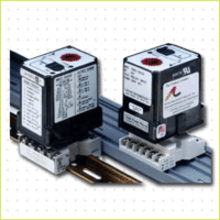
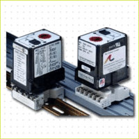
Product Description
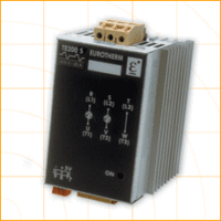
AP 1680/1690 Configurable Limit Alarms
AP 1680/1690 Configurable Limit Alarms Action Pak model AP1690 dual setpoint limit alarms offer flexible, wide ranging AC input and relay output capability. Voltage spans from 100mV to 200VAC and current spans from 10mA to 100mAAC can be field configured. For current input spans of 1 to 5 Amps a 0.1W (0.1%) shunt resistor (Model #C006) is available. The model offers configurable latching, failsafe, and HI/LO operation. The AP1690 also includes 0.25% to 50% adjustable deadbands and selectable 120/240VAC operation.
Diagnostic LED
Models AP1680-2000 and AP1690-2000 are equipped with dual function diagnostic LED. The green center LED indicates line power and input signal status. Active line power is indicated by an illuminated LED. If the center LED is off, check line power and the wiring connection. If the input signal is above 100% full scale, the LED will flash at approximately 8Hz. Below 0%, the flash rate is approximately 4Hz.
Operation
The field configurable AP1680 and AP1690 limit alarm setpoints can be configured for HI, LO, latching or failsafe trip operation. Non-latching HI and LO setpoints have respective HI and LO deadbands. In a tripped condition, the setpoint is exceeded and the appropriate red LED will illuminate. The trip will reset only when the process falls below the HI deadband or rise above the LO deadband. To reset a latched setpoint the signal must be in the safe region and the line power turned off for at least 5 seconds. For proper deadband operation, a HI setpoint must always be set above a Lo setpoint.
Calibration
Note: To maximize thermal stability, final calibration should be performed in the operating installation, allowing approximately 1 – 2 hours for warmup and thermal equilibrium of the system.
Setpoint: Set deadband at its minimum (about 20 turns Counter Clockwise) before adjusting the setpoint. With the specified trip voltage or current input applied, adjust setpoint until the relay trips. For HI trip calibration, start with the setpoint above the desired trip. For LO trip calibration, start below the desired trip.
Deadband: Set deadband to its minimum (about 20 turns Counter Clockwise). Set setpoint to desired trip. Adjust voltage/current input until relay trips. Readjust deadband to 50% (20 turns CW). Set voltage/current input to desired deadband position. Slowly adjust deadband until relay untrips.
TECHNICAL SPECIFICATION ( AP1680-2000/AP1690-2000)
Input
Voltage Input:
- Range: 100mV to 200V AC
- Impedance: >100K Ohmns
- Overvoltage: 300VAC, max
Current Input:
- Full Scale Range: 10mA to 100mA
- Impedance: 20 Ohms, typical
- Overcurrent: 200mA, max
Frequency range
DC 40-400Hz, factory calibrated at 60Hz
- Common Mode (Input toGround): 1000V, max
LED Indications
Input Range (Green)
- >100% input: 8Hz flash
- <0% input: 4Hz flash
Setpoint (Red)
- Tripped: Solid red
- Safe: Off
Limit Differential
.25% to 50% of span
Response Time: Dynamic Deadband:
Relay status will change when proper setpoint/process condition exists uninterrupted for 100ms
Normal Mode (analog filtering)
<250ms, (10-90%)
Setpoint:
Effectivity: Setpoints are adjustable over 100% of the selected input span.
- >50mV/5mA: .1% of full scale
- <50mV/5mA: .2% of full scale
Stability
- Line Voltage: ± .01%, max.
- Temperature: ± .025% of full scale/°C, max.
Common Mode Rejection
DC to 60Hz: 120dB
Isolation
1000 VDC between contacts, input and power
ESD Susceptibility
Meets IEC 801-2, Level 2 (4KV)
Humidity (Non-Condensing)
- Operating: 15 to 95% (@ 45°C)
- Soak: 90% for 24 hours (@ 45°C)
Temperature Range
- Operating: -15 to 60°C (5 to 140°F)
- Storage: -25 to 70°C (-13 to 158°F)
Power
- Consumption: 2W typical, 5W max
- Standard: selectable 120/240VAC, ±10%, 50-60Hz
- Optional: 9 to 30VDC, inverter isolated
Weight
.64 lbs
Agency Approvals
- CSA certified per standard C22.2, No. M1982.
- UL recognized per standard UL508.

