Product Description
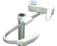
V565 Loop-Powered LCD Indicator
The V565 Loop-Powered LCD Indicator is a loop-powered digital process indicator which derives its power entirely from the 4-20mA or 10-50mA signal being measured. No local power is required at the point of measurement.
The 3-1/2 digit, 0.8″ high Liquid Crystal Display (LCD) provides clear visibility up to a distance of 30 feet, and can be easily calibrated to the required range. Zero and fullscale can be set
anywhere between -1999 and 1999. Span can be from 0 to 3998 counts (100 count minimum span).
The V565 provides linear and square root operation, permitting direct flow readings from differential pressure origins (e.g., orifice plates). The V565 is also equipped with selectable direct/reverse display gain. Reverse operation provides a decreasing count with an increasing input. A trailing, dummy, zero allows display readings to ±19990. The decimal point position is switch selectable and can be independently set to any of four positions (1.9.9.9.).
Application
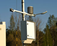
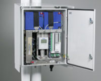
The V565 is useful in any application requiring a wide-ranging 3˚ digit display from a 4-20mA or 10-50mA current source. The V565’s standard NEMA 4X housing enables indoor or outdoor installation with protection from sleet, corrosion, moisture,
chemicals, and even hose directed water or severe condensation. The V565 is ideal for displaying process variables in local and remote areas where line power is not available or impractical.
The V565 is entity approved by FM for intrinsically safe operation in Class I, II, and III, Division 1 & 2 hazardous locations when installed per manufacturer’s drawing 790-0029-00.
The V565 is also intrinsically safe per CSA for operation with the following housings when installed per manufacturers drawing 790-0025-00: panel housing: Class I, Groups A, B, C and D; conduit housing: (Opt C) Class I, Groups A, B, C and D. Class II, Groups E, F and G. Class III; EP housing: Class I, Groups C and D. Class II, Groups E, F and G.t. Loop Drop of 1 Volt
The supply requirement of model V565 is only 1.0 volt on a 4- 20mA current loop. This is beneficial in applications where intrinsic safety barriers are used and voltage compliance is at a premium. The V565 can provide an extra 3-5 volts of loop drive above standard loop-powered indicators.
Display Configuration
The V565 is easily configured using the switches and potentiometers on the display board. To configure the unit, refer to the function switches diagram below.
1. Set jumpers W1 & W2 to “Normal” or “Reverse” for direct or reverse count, respectively.
2. Set switch S2 for the correct current input: “Linear” for linear operation and “Square Root” for square root operation.
3. Set switch S1 accordingly to obtain the desired zero and span count values.
4. Fine tune the display using the “Display Zero” and “Display Span” trimpots. Use table 1 for square root display configuration.
Display readings calibrated for either 4-20mA or 10-50mA linear scaling will maintain calibration within 1% if switched to the other range. If readings are inaccurate, the input amplifiers may require adjustment. See Factory Calibration.
Note: Span refers to counts from minimum to full-scale input.
Calibration
The V565’s input and square root zero amplifiers are pre-calibrated at the factory (4-20mA). For best accuracy, the input amplifiers should be recalibrated when the square root function is selected or the current input is changed (10-50mA). Perform recalibration at an ambient temperature of 20-30°C (68-86°F).
1. Connect DVM (-) to “TP0” (gnd) of plug P1 and (+) to “ZERO” and “SQRT” for zero and square root calibration, respectively.
2. Apply 4.000mA or 10.000mA to the input. Set S2-1 accordingly.
3. Adjust the “Input Zero” and “Square Root Zero” potentiometers until the DVM reads 0.000 volts (Zero: ±0.0005V; Sqrt: ±0.001V). Note that Input zero must be calibrated first. Remove the DVM leads from P1 before configuring the display or errors may occur.
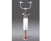
V565 EP Installation
1. Conduit for field wiring should be attached to the 3/4″ NPT threaded hole provided. The display board can be rotated to permit either top or bottom service.
2. Unscrew the cover. Remove the four (4) outermost phillips screws from the black display plate and remove the indicator assembly.
3. Install the T600/T700 series transmitter if required. Mounting hardware is included.
4. Connect the field wiring to the indicator assembly terminals (and Transpak if installed). Connect the ground wire to the EP case. Route the wiring through the bracket grommet and conduit port.
5. Replace the indicator assembly.
6. Reinstall the cover with at least 5 clockwise revolutions. Do NOT use sealant on the threads.
Specifications
Input Current Ranges:
4-20mA and 10-50mA, switch selectable
Input Current Limits:
- Minimum: 3mA
- Maximum: 220mA (Fuse)
Input Voltage Drop:
- 4-20mA: 1 volt max. @ 20mA
- 10-50mA: 1.4 volt max @ 50mA
Power Consumption:
2.5mW maximum @ 3.5mA input
Display Reading Update
2 readings per second
Readout Display:
- Type: 0.8″ High Liquid Crystal, 3-1/2 digit (1999)
- Decimal Point Indication: Switch-selectable, four positions 1.9.9.9.
- Dummy Zero: Switch-selectable trailing zero, e.g., 19990
- Direction: Jumper-selectable,
- Underrange (below -1999): displays -1
- Overrange (above +1999): displays 1
Display Calibration:
- Zero (4mA/10mA): Adjustable from -1999 to 1999
- Span (20mA/50mA): Adjustable from 0 to 3998
Accuracy (@ 25 ±5°C):
- Linear:<±0.1% of span counts, ±1 count.
- Square-Root: <±0.1% of span counts, ±1 count (from 1% to 100% of span)
Ripple Rejection:
1 count error with 1mA p-p ripple @ 50Hz
Screws (V565/V565C):
- Front Panel: 10-32, brass with corrosion resistant stainless steel plating: MIL-W-52263C (MR)
- Rear Electrical: 6-32, nickel plated brass
Terminals:
- Standard: 6-32 screw (accepts 0.2″ ring lug)
- Conduit mount (Opt C): Screw clamp, 12 AWG wire gauge, max.
Temperature Coefficient:
(Std Calibration: -10 to 70°C; Linear mode):
- Zero: ±0.1 counts/°C, ±1 count, typical. ±0.2 counts/°C, ±1 count, max.
- Span (1000 to 3998): ±150ppm/°C, ±1 count, max.
- Span (100 to 999): 150ppm/°C + .95(1000 – Span), ±1 count, max.
Temperature Coefficient (Square-root):
Equivalent to 1uA/°C max. input drift
Temperature Range:
- Standard: -10 to 70°C (14 to 158°F)
- Storage: -55 to 80°C (-67 to 176°F)
Humidity (with conformal coat @25°C):
5 to 95% RH, non-condensing
Weight:
- V565: 15 oz.
- V565C: 2.2 lbs.
- V565 EP: 11 lbs.
Agency Approval:
- FM approved intrinsically safe for hazardous locations, certificate No.3V1A5.AX. Contact factory for installation drawings.
- CSA approved intrinsically safe for hazardous locations, (File No.LR422272-45).
FM Entity Parameters:
- Vmax=33V
- Imax=178.5mA
- Ci=0mF
- Li=0mH