Product Description
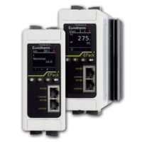
T723 Thermocouple
The T723 Thermocouple offers a choice of J/K/T or E/R/S input ranges and 2 output ranges, which are field selectable via top-accessed DIP switches (see Tables 1-2). The T723 provides 600 VDC input to output isolation with outputs of either 4-20mA or 10-50mA. The current output is linear to the equivalent mV thermocouple signal and non-linear to temperature, which is useful in data acquisition systems that utilize linearizing software. Upscale burnout (maximum output with an open thermocouple) is standard.
The T723 has 80% zero and span adjustability within any user selected input ranges shown in Table 1 and 2. For example, Range K1 of Table 1 specifies 0° to 500°C with a minimum span of 100°C (500°-100° = 400°, or 80%). This 80% adjustability allows the user to field calibrate the unit from the maximum (0 to 500°) down to any minimum (100°C) span (e.g. 14°C to 114°C) as long as that adjusted span remains within the selected 0 to 500°C range. The same is true for any user selectable range: all spans are field adjustable from 20% (minimum span) to 100% of the specified range.
Application
The T723 is useful in any application requiring isolation of a 2-wire loop current from a thermocouple input. Typical applications include energy management and data acquisition such as monitoring remote boiler temperatures. The output of the T723 can interface with a digital meter for direct display or interface with a computer for monitoring and control applications.
The T723 is FM approved for intrinsically safe operation in Class I, Division 1, Groups A, B, C, and D; Nonincendive Class I Division 2, Groups A, B, C and D, and Classes II & III, Division 2, Group G hazardous locations when installed per manufacturer’s drawing 790-0024-00. Refer to model F723 for NEMA 4, FM/CSA/CENELEC approved explosion proof, field mount housing.
Calibration
| Input Range: | J1 |
| Output Range: | 4-20mA |
- Open the access lid on the top of the unit (see Top View Diagrams).
- Select the output range using switch S6. The CLOSED position selects a 10-50mA output. The OPEN position selects a 4- 20mA output.
- Select the input range from Table 1 or 2 and configure switches S1 through S5.
- Connect the input to a calibrated thermocouple source. Connect the output loop to a voltage supply and monitor the output current. Refer to Terminal Wiring.
- Set the calibrator to the desired minimum.
- Adjust the coarse zero rotary switch to obtain an output of aproximately 4mA or 10mA. Adjust the fine zero for exact calibration.
- Set the calibrator to the desired maximum and perform similar adjustments using the coarse span switch and fine span potentiometer.
- Repeat fine zero and span adjustment for maximum accuracy
Field Mounting
The T723 is designed for installation in industrial field environments. A sealed, diecast aluminum housing protects against corrosion, moisture, dust and electrical noise such as radio frequency (RFI) and electromagnetic (EMI) interference. All circuit boards are urethane coated for environmental protection and FM approval.
For protection against extreme moisture, hosedirected water (NEMA 4) or hazardous environments, use model F723. The F723 2-wire transmitter offers the same wide-ranging features of the T723, but includes a rugged Explosion Proof (EP) NEMA 4 enclosure with standard, 1/2″ and 3/4″ FPT ports for operation in harsh process environments.
TECHNICAL SPECIFICATION (T723)
Input Span Range (Max/Min)
See Tables 1 and 2
Leadwire Resistance Effect
<0.25 uV/Ohm
Burnout Detection Current
250nA, max.
Output Span
4-20mA/10-50mA, switch selectable
Minimum Output Current
3.3mA, typical
Maximum Output current
4-20mA: 24mA, typical
10-50mA: 58mA, typical
Supply Voltage Range
4-20mA: 12 to 80VDC
10-50mA: 12 to 60VDC
Maximum Change in Supply
0.05% of span
Maximum Change in Load Effect
0.05% of span
Loop Voltage Drop
12VDC @ 20mA
Stability
- Zero: ±0.02% of span/°C, max.
- Span: ±0.01% of span/°C, max.
Overall Accuracy (Includes Linearity, Hysteresis, Stability)
±0.5% of any adjusted span, max.
Zero and Span Adjustability
80% of any selected range
Repeatability
±0.05% of span, typical
Cold-Junction Error (Ambient)
- J/K/T/E Inputs
- 0 to 80°C: 1°C, typical
- -40 to 0°C: 3°C, typical
- R/S Inputs
- 0 to 80°C: 2°C, typical
- -40 to 0°C: 5°C, typical
Response Time
100ms, typical; 200ms, max.
Output Ripple
0.1% of span, rms, typical
RFI Effect (5W, 470MHz at 3 Ft.)
<1% of span error, typical
Isolation
600V DC or peak AC max., input to output to case
Temperature Range
Operating: -40 to 80°C (-40 to 176°F)
Weight
0.56lbs
Agency Approvals
FM approved intrinsically safe for hazardous locations, certificate No. 2M2A5.AX.