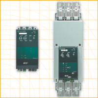
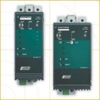
Product Description
WV418 Signal Conditioner
WV418 Signal Conditioner
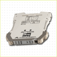
The Ultra SlimPak II is an exciting new line of isolating signal conditioners from Action Instruments with greater accuracy and better stability than virtually any other signal conditioners on the market today. The Ultra SlimPak II features Smart Power, which eliminates wasted power for low loop resistance loads in the current output mode.
The WV418 supports 2-wire, 3-wire or 4-wire Pt100 RTDs with alphas of either 0.00385 or 0.00392, as well as Cu10. Ranges are DIP switch selectable or (optionally) PC programmable. Outputs include 0-10V, 0-20mA and 4-20mA.
Smart Power
The Ultra SlimPak II uses Smart Power to control its output supply. Smart Power automatically adjusts the the voltage to drive the output loop to the required current. A low impedance current loop will subsequently require less voltage than a loop with higher impedance. Previous designs provided only a single supply at the highest voltage required to drive the highest impedance load. Using Smart Power results in power savings and reduces the operating temperature of the signal conditioner.
Enhanced LED Diagnostics
Other than when executing the pushbutton calibration routine, the LEDs blink under the following conditions:
GREEN:
- Flashes at 2Hz when the input is under range.
- Flashes at 8Hz when the input is over range.
RED:
- Flashes at 2Hz when the output is under range.
- Flashes at 8Hz when the output is over range.
An Under Range condition exists when the signal is lower than the operational low value minus 6.25% of the operational span. An Over Range condition exists when the signal is higher than the operational high value plus 6.25% of the operational span.
A voltage output short circuit may cause an under range condition (RED blinking at 2Hz rate). A current output open circuit may cause an over range condition (RED blinking at an 8Hz rate).
There could be two or more LEDs blinking at the same time, which means the module has more than one error condition. Only when all error conditions have been removed, will the LEDs be back to normal (Green ON, Red and Yellow Off).
Configuring Modules
Unless otherwise specified, the factory presets the Model WV418 as follows:
| Input: | Pt100, 3-wire, alpha = 0.00385 |
| Range: | -200 to 600°C |
| Output: | 4-20mA |
| Reverse Out: | Off |
| Remote Cal: | Off |
- For other ranges, refer to the SWITCH SETTINGS table. Reconfigure switches S1 and S2 for the desired input type and range.
- Set position 1 of S2 to ON if a WVC16 will be utilized and remote calibration capability is desired.
- Set position 2 and 3 of S2 for the desired output type and range.
- Set position 4 of S2 to ON for reverse output operation.
- Set positions 1-7 of S1 and positions 5 & 6 of S2 for the desirred input range.
It is also possible to remotely select the setpoints using an Ethernet connection and the optional WVC16 WebView Communications Interface module.
Alarms
When used with the optional WVC16 communications module, the WV418 supports up to 3 alarms, which can be configured as high limit, low limit and a timer for routine maintenance.
WV16 Communications Interface (Optional)
TThe WVC16 Communications Interface adds functionality never before found in a signal conditioning system. The WVC16 interfaces with Ultra SlimPak II devices via an internal infrared communications link (no programming required) and provides the ability to connect as many as 32 modules to the intranet, allowing the user to view process data on a near real time basis, perform data logging functions on specified modules, calibrate the signal conditioners remotely, and view diagnostic information.
The WVC16 contains a web page server and an e-mail server. Browsers supported include Internet Explorer 5 or later and Netscape Navigator 4.7 or later. The user has the ability to have setpoint trip conditions generate an email message for up to 10 recipients. The module also contains a countdown timer that can be used to notify when routine maintenance is required, such as re-calibration. The internal temperature of the module can also be monitored. All memory to support the signal conditioner’s historical data, storage of the web pages and all e-mail messages is contained in the WVC16.
The WVC16 downloads a JAVA applet to the client’s computer. The applet provides access to the signal conditioner’s data, which includes the following:
- Module configuration summary
- Module configuration editing
- Diagnostic/warning status
- Alarm setup & status
- E-mail setup, editing & address book
- Process variable viewing
Calibration
The calibration procedure is contained in the Installation & Calibration Instructions document, which is available on our website (www.actionio.com). You can also obtain it by telephoning Action technical support (703- 669-1318).
Note that Custom Calibration (option C620) is available from the factory (settings MUST be within the units specifications). For a C620, specify the following:
- a) Input Type, Range & Units (mA, mV, V).
- b) Output Type, Range & Units (ma, mV, V).
- c) Reverse Output (ON/OFF)
TECHNICAL SPECIFICATION (WV418)
| Ranges | Pt100 RTDs | ||||||||||||||||||||||||||||||||||||||||||||||
|
|||||||||||||||||||||||||||||||||||||||||||||||
| Cu10 RTDs | |||||||||||||||||||||
|
|||||||||||||||||||||
Inputs
Sensor Types
Pt100, 0.00385 alpha & 0.00392 alpha
Cu10
Sensor Connection
2-wire, 3-wire or 4-wire RTD
RTD Excitation
Pt100: 0.45mA, ma
Cu10: 5.0mA, max
Lead Wire Resistance
40% of the base sensor resistance maximum or 100 ohms (whichever is less)
Lead Wire Effect
Changing from 0 ohm lead resistance (each lead) to maximum allowed lead resistance:
Error <1% of largest span PT and Cu ranges; -200 to 600°C for Pt and –200 to 260°C for Cu.
Pushbutton Adjustment (Inputs >10mV)
- Effective zero offset: >95%
- Effective span turn down: >95%
Local Range Selection
By DIP switch
Output Voltage
0 to 10V
Source Impedance
<10 ohms
Drive
10mA
Current
0 to 20mA
Source Impedance
>100k ohms
Compliance
20V
Output Accuracy
0.05% of Full Scale
Response Time
100mSec (10 to 90%)
Stability
±100ppm of full scale/°C (±0.01%/°C)
CMRR
120dB @ DC, >90dB @ 60Hz, or better
Isolation
>1800VDC or peak AC between input, output & power.
ESD Susceptibility
Capable of meeting IEC 801-2 level 3 (8kV)
Humidity (non-condensing)
- Humidity (non-condensing) 15 to 95% RH @45°C
- Soak: 90% RH for 24hrs @60°C
Temperature
- Operating: 0 to 60°C
- Storage: -25 to +85°C
Power
- 9 to 30VDC
- 1.0W typical, 2.0W max
Host Module Interface
IR link
Size
DIN rail case – refer to Dimensions drawing
Agency Approvals (EMC & Safety)
CE, EN61326, EN61010-1 UL & CSA combined mark